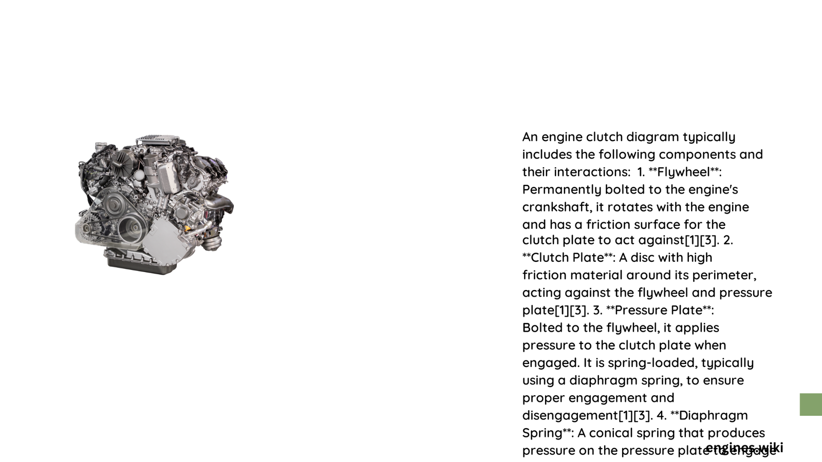
An engine clutch diagram represents a sophisticated mechanical interface that enables smooth power transmission between an engine’s crankshaft and transmission input shaft. This intricate system allows controlled engagement and disengagement of rotational energy, facilitating gear shifts and preventing mechanical stress during vehicle operation.
What Comprises an Engine Clutch Diagram?
Core Mechanical Components
The engine clutch diagram reveals several critical components working in precise synchronization:
- Flywheel Elements
- Directly attached to engine crankshaft
- Provides rotational mass and engagement surface
-
Typically manufactured from high-strength cast iron
-
Clutch Disc Specifications
- Central power transmission interface
- Constructed with friction material
- Contains precision-engineered spline connections
How Does Clutch Engagement Mechanism Function?
Hydraulic Actuation Process
┌─────────────────────┐
│ Clutch Pedal Input  │
└──────────┬──────────┘
           ▼
┌─────────────────────┐
│ Master Cylinder     │
│ Develops Pressure   │
└──────────┬──────────┘
           ▼
┌─────────────────────┐
│ Slave Cylinder      │
│ Transfers Motion    │
└──────────┬──────────┘
           ▼
┌─────────────────────┐
│ Clutch Fork Movement│
└─────────────────────┘
Precise Dimensional Characteristics
| Component | Typical Diameter | Material | Thickness |
|---|---|---|---|
| Clutch Disc | 11-12 inches | Steel/Friction | 0.25-0.5 inches |
| Flywheel | 14 inches | Cast Iron | Variable |
| Pressure Plate | 11-12 inches | Steel | 0.5 inches |
What Determines Clutch Performance?
Critical performance factors include:
- Friction material quality
- Spring tension characteristics
- Hydraulic system precision
- Alignment tolerances
- Thermal management capabilities
Technical Challenges in Clutch System Design
Engineers must address complex challenges:
- Managing heat dissipation
- Minimizing wear during engagement
- Maintaining consistent friction coefficients
- Ensuring reliable hydraulic pressure transmission
- Reducing mechanical vibration
Advanced Diagnostic Considerations
Professionals evaluate clutch system health through:
- Pedal feel and travel distance
- Engagement smoothness
- Unusual noise during operation
- Slippage indicators
- Hydraulic system integrity
Maintenance Recommendations
- Regular hydraulic fluid checks
- Periodic throwout bearing inspection
- Monitoring clutch disc friction surface
- Verifying alignment tolerances
- Assessing spring tension characteristics
Conclusion

Understanding the engine clutch diagram provides critical insights into automotive power transmission mechanics, revealing a complex yet precisely engineered system that enables smooth vehicle operation.
