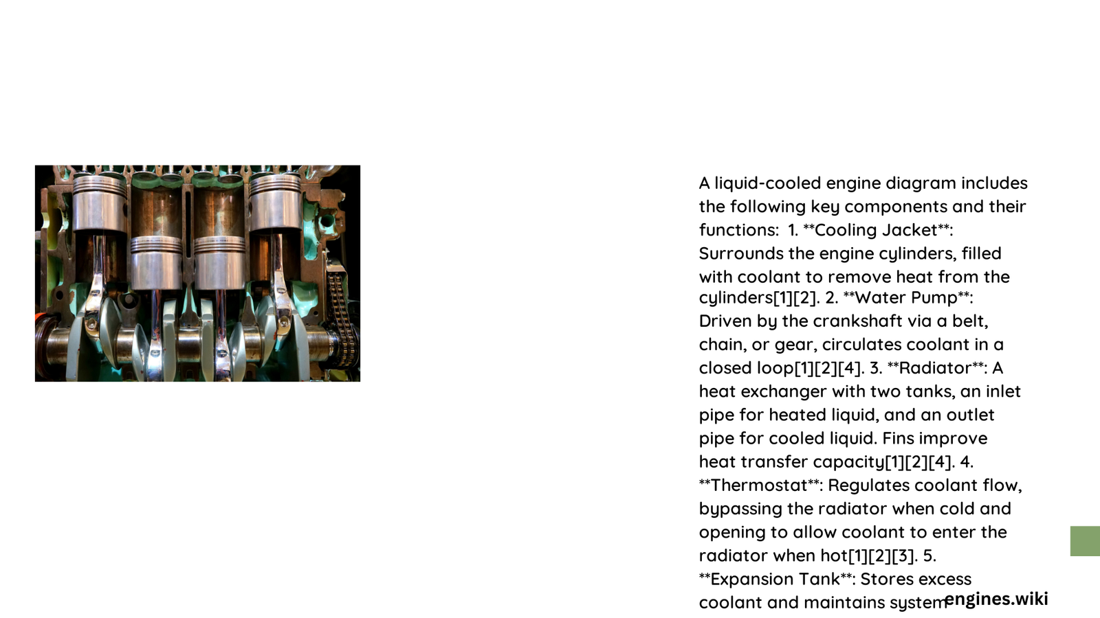
A liquid cooled engine diagram represents a sophisticated thermal management system that efficiently dissipates heat generated during combustion through a complex network of interconnected components. This intricate design involves precise circulation of coolant through specialized passages, utilizing principles of thermodynamics to maintain optimal engine temperature, prevent overheating, and ensure maximum performance and longevity of automotive powertrains.
What Makes Liquid Cooling Essential for Modern Engines?
Liquid cooling has revolutionized engine thermal management by providing superior heat dissipation compared to traditional air-cooled systems. The fundamental advantage lies in its ability to:
- Maintain consistent engine temperatures
- Distribute heat more uniformly
- Reduce thermal stress on critical engine components
- Enable higher compression ratios
- Improve overall engine efficiency
How Does Coolant Circulate Through the Engine?
Coolant Flow Mechanism
The liquid cooling system operates through a meticulously designed circulation path:
- Water Pump Initiation
- Drives coolant through engine passages
- Generates consistent fluid movement
-
Prevents localized heat accumulation
-
Thermal Regulation Points
- Thermostat controls temperature-based flow
- Manages coolant redirection between radiator and engine block
- Ensures rapid warm-up and stable operating conditions
What Are the Primary Components in a Liquid Cooled Engine Diagram?
| Component | Primary Function | Material Composition |
|---|---|---|
| Radiator | Heat dissipation | Aluminum tubes/fins |
| Water Pump | Coolant circulation | Cast iron/aluminum |
| Thermostat | Temperature regulation | Wax-filled metal valve |
| Engine Block | Coolant passage creation | Cast iron/aluminum |
What Technical Principles Govern Liquid Cooling?
Heat Transfer Dynamics
Liquid cooling leverages fundamental thermodynamic principles:
- Specific Heat Capacity: Water-based coolants absorb significant thermal energy
- Thermal Conductivity: Efficient heat transfer between engine components
- Fluid Dynamics: Controlled circulation prevents localized temperature variations
How Do Engineers Design Optimal Cooling Passages?
Engineers meticulously design cooling passages considering:
- Geometric complexity
- Material thermal properties
- Flow resistance
- Heat transfer coefficients
What Challenges Exist in Liquid Cooling Design?
Critical challenges include:
- Preventing corrosion
- Managing pressure variations
- Minimizing fluid friction
- Ensuring long-term reliability
Calculation of Thermal Performance
The heat transfer equation quantifies cooling efficiency:
[
Q = \dot{m} \times c_p \times \Delta T
]
Where:
– ( Q ): Heat transferred
– ( \dot{m} ): Coolant mass flow rate
– ( c_p ): Specific heat capacity
– ( \Delta T ): Temperature difference
Emerging Technologies in Liquid Cooling
Future developments focus on:
- Nano-enhanced coolants
- Advanced computational fluid dynamics
- Adaptive thermal management systems
- Integration with electric vehicle architectures
Conclusion

A liquid cooled engine diagram represents a pinnacle of thermal engineering, balancing complex physical principles with practical automotive requirements.
