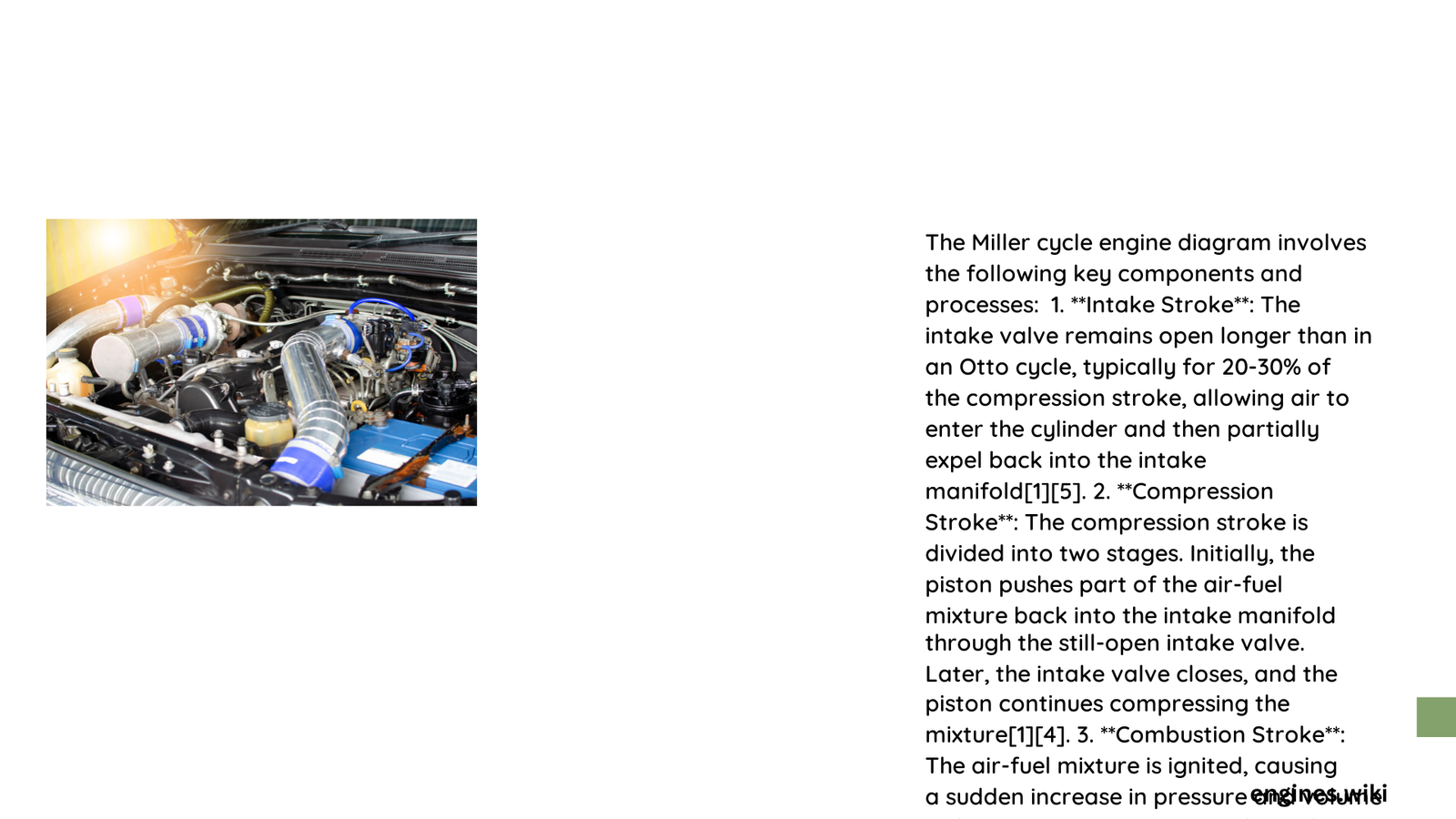
The Miller cycle engine represents a sophisticated thermodynamic approach to internal combustion, strategically manipulating intake valve timing to achieve superior thermal efficiency. By extending the expansion stroke and reducing effective compression through innovative valve control, this advanced engine design challenges traditional four-stroke principles, offering remarkable improvements in fuel economy and reduced emissions through precise engineering interventions.
What Makes Miller Cycle Engine Diagram Unique?
How Does Valve Timing Transform Engine Performance?
The Miller cycle engine diagram reveals a revolutionary approach to valve operation. Unlike conventional engines, the intake valve remains open during part of the compression stroke, creating a distinctive thermodynamic cycle with several critical advantages:
Key Valve Timing Characteristics
- Early Intake Valve Closure (EIVC)
- Reduced Effective Compression Ratio
- Extended Expansion Stroke
What Components Define the Miller Cycle?
| Component | Function | Unique Characteristics |
|---|---|---|
| Intake Valve | Controls Air-Fuel Mixture Entry | Variable Timing Mechanism |
| Turbocharger | Compensates Reduced Compression | Forced Induction System |
| Piston | Energy Conversion Mechanism | Optimized Stroke Length |
| Exhaust Valve | Manages Combustion Gases | Precise Timing Control |
Why Implement Miller Cycle Technology?
Performance Advantages
- Enhanced Thermal Efficiency
- 35-40% improved efficiency
- Reduced heat losses
-
Optimized energy conversion
-
Emissions Reduction
- 20-30% lower NOx emissions
- Cleaner combustion process
- Environmentally friendly design
How Does Miller Cycle Differ from Traditional Engines?
Fundamental Design Variations
- Intake Stroke Modification
- Partial air pushback during compression
- Reduced effective compression ratio
-
Compensated through forced induction
-
Expansion Stroke Optimization
- Longer power generation phase
- More efficient energy extraction
- Improved overall thermodynamic performance
What Technical Challenges Exist?
Implementation Complexities
- Advanced valve timing mechanisms
- Precise turbocharging requirements
- Higher manufacturing costs
- Complex control systems
Materials and Manufacturing Considerations
Advanced Engineering Solutions
- Valve Materials: Titanium alloys
- Piston Composition: Lightweight aluminum composites
- Precision Manufacturing: CNC machining techniques
- Control Systems: Sophisticated electronic management
Potential Future Developments
Emerging Research Directions
- Hybrid Miller cycle configurations
- Integration with electric powertrains
- Advanced computational modeling
- Nano-material component development
Technical Performance Metrics
| Performance Parameter | Typical Value | Improvement Percentage |
|---|---|---|
| Thermal Efficiency | 38-42% | +15-25% vs. Otto Cycle |
| NOx Emissions | <2 g/kWh | -20-30% Reduction |
| Fuel Consumption | 5-7 L/100km | +10-15% Efficiency |
Practical Implementation Strategies
Recommended Design Approaches
- Integrate variable valve timing
- Utilize advanced turbocharging
- Implement precise electronic controls
- Design lightweight, durable components
Conclusion

The Miller cycle engine diagram represents a sophisticated engineering solution, transforming traditional combustion principles through intelligent valve timing and advanced thermodynamic strategies.
